


If you have ever wondered what is a brake assist system, the simplest answer is that it is a safety technology designed to help a vehicle or machine generate stronger braking force when the operator suddenly applies the brakes. A brake assist system detects rapid or emergency brake-pedal application and helps increase braking pressure so the braking system can respond more effectively.
The technology is particularly important during emergency braking, when a driver may press the brake pedal quickly but not apply enough force to achieve the maximum available braking performance. Brake assist can help bridge that gap by using hydraulic, vacuum, electro-hydraulic, or electronically controlled assistance depending on the system design.
Although brake assist is most commonly associated with passenger cars, commercial vehicles, and automotive braking systems, the engineering principles behind assisted braking are also relevant to industrial and marine environments. Marine electrical engineers may encounter electrically controlled braking arrangements on cranes, winches, hoists, davits, deck machinery, and other equipment where controlled stopping and holding are essential.
For Electrical Marine Solutions, understanding braking controls is part of the wider discipline of electrical troubleshooting, control systems, marine automation, motor control, preventive maintenance, and industrial electrical engineering. A brake circuit may involve relays, contactors, sensors, PLC logic, motor drives, solenoids, power supplies, and safety interlocks.
This guide explains what is a brake assist system, how it works, its components, types, applications, faults, inspection procedures, maintenance requirements, and the relationship between braking assistance and modern electrical control systems.
Quick Answer: What Is a Brake Assist System?
A brake assist system is a braking technology that helps increase braking force during sudden or emergency braking. It detects rapid brake-pedal application or another emergency-braking condition and assists the braking system in producing higher hydraulic or electronically controlled braking pressure.
The main purpose is to reduce stopping distance and help the operator achieve effective braking performance when a sudden reaction does not produce enough pedal force.
In automotive applications, brake assist commonly works alongside systems such as anti-lock braking systems (ABS), electronic stability control, traction control, and electronic braking controls. In industrial and marine equipment, related assisted-braking principles can be implemented through hydraulic systems, electric actuators, spring-applied brakes, solenoids, motor drives, sensors, and programmable control systems.
For marine and industrial electrical engineers, the important point is that braking is not only a mechanical function. Modern braking equipment can depend heavily on electrical power, control logic, feedback signals, safety circuits, and automation.
Featured Snippet: How Does Brake Assist Work?
A brake assist system works by detecting a rapid or emergency braking command and helping the braking mechanism apply additional force. In a conventional hydraulic braking system, the driver creates hydraulic pressure by pressing the brake pedal. Brake assistance supplements that effort so the brake system can reach a higher braking pressure more quickly.
Electronic systems may use pedal-position sensors, pressure sensors, control modules, valves, pumps, and actuators to determine when assistance is necessary. In industrial machinery, a controller may instead monitor a stop command, motor speed, load condition, limit switch, or emergency-stop circuit before activating a braking device.
The exact operation depends on the equipment architecture. A vacuum brake booster, electro-hydraulic brake system, electronically controlled actuator, or spring-applied electromagnetic brake can all provide different forms of braking assistance.
Key Takeaways
A brake assist system provides additional braking assistance when rapid or emergency braking is detected. Its purpose is to help the braking system reach effective braking force quickly.
The technology should not be confused with ABS. Brake assist helps generate or increase braking force, while ABS primarily prevents wheel lock during hard braking.
Modern braking systems can contain mechanical, hydraulic, pneumatic, electrical, electronic, and software-controlled components.
In marine and industrial environments, electrically controlled braking is particularly important for cranes, winches, hoists, deck machinery, lifting equipment, and motor-driven systems.
Regular inspection is essential because a braking fault can create serious safety risks. Electrical engineers should inspect power supplies, control circuits, sensors, relays, contactors, solenoids, actuators, interlocks, and PLC logic where applicable.
What Is a Brake Assist System?
To understand what is a brake assist system, it is useful to first understand the limitation of conventional braking. In a basic hydraulic brake arrangement, the operator creates braking pressure by pushing the brake pedal. The harder and faster the pedal is applied, the greater the braking force can become.
During an emergency, however, a person may react quickly without applying enough force. This can happen because of panic, unfamiliarity, fatigue, poor seating position, or simply the short amount of time available to react. Brake assistance is designed to help compensate for this limitation.
A brake assist system recognizes characteristics associated with emergency braking and supports the braking mechanism. Depending on the design, assistance can be generated through vacuum pressure, hydraulic pressure, electric pumps, electronic actuators, or other control technologies.
In modern vehicles, brake assist may communicate with other electronic safety systems. The braking controller can receive information from sensors and coordinate braking pressure with ABS and stability-control functions.
In industrial and marine applications, the concept is broader. A braking system may be activated by an operator command or an automated controller. The system could use an electromagnetic brake, hydraulic brake, spring-applied brake, or motor-integrated braking arrangement. Electrical control determines when the brake releases, applies, modulates, or holds.
That is why braking technology increasingly overlaps with electrical engineering, automation, instrumentation, and safety control.
How Does a Brake Assist System Work?
The operation of a brake assist system begins with an input. In a road vehicle, this input is normally the brake pedal. In industrial machinery, the input could be a stop command, emergency-stop button, PLC output, limit switch, or motor-control signal.
Sensors or mechanical components determine whether the braking command represents normal or emergency operation. If the system identifies an emergency condition, it activates an assistance mechanism.
In a vacuum-assisted automotive system, the brake booster uses pressure differences to multiply the force applied by the driver. In electro-hydraulic systems, an electric pump can create hydraulic pressure independently or supplement pressure created by the driver.
In electronically controlled equipment, a controller may activate a solenoid valve or electromagnetic actuator. The controller can also monitor feedback to confirm that the brake has actually engaged.
Marine machinery introduces additional considerations. A winch brake, for example, may need to hold a suspended load safely after a motor stops. The control system can remove power from an electromagnetic brake, allowing a spring-applied mechanism to engage. This is a fundamentally different application from automotive emergency braking, but the same engineering objective exists: controlled and reliable stopping.
The system therefore depends on correct coordination between the command, actuator, mechanical brake, electrical supply, and feedback system.
Working Principle of Brake Assistance
The working principle can be summarized as detect, decide, assist, apply, and verify.
First, the system detects an operator action or control command. In a car, this may involve pedal movement or pedal speed. In industrial machinery, it may involve a stop signal, motor speed, load sensor, or emergency circuit.
Second, the controller or mechanical mechanism determines the appropriate braking response. The decision can be instantaneous because braking systems are safety-critical.
Third, assistance is applied. This might involve hydraulic pressure, vacuum assistance, an electric motor, a solenoid, or another actuator.
Fourth, the braking mechanism applies force to slow or stop the moving equipment.
Finally, feedback may confirm the brake position or system status. Modern automated machinery can use sensors to determine whether the brake is released, partially engaged, or fully engaged.
In marine automation, this final verification stage can be extremely important. A PLC-controlled system may need confirmation that a brake has engaged before allowing another operation to proceed. For example, a crane control system may prevent a lifting sequence from continuing if the brake-position feedback is missing.
This illustrates why brake control should be considered part of the complete control system rather than an isolated mechanical component.
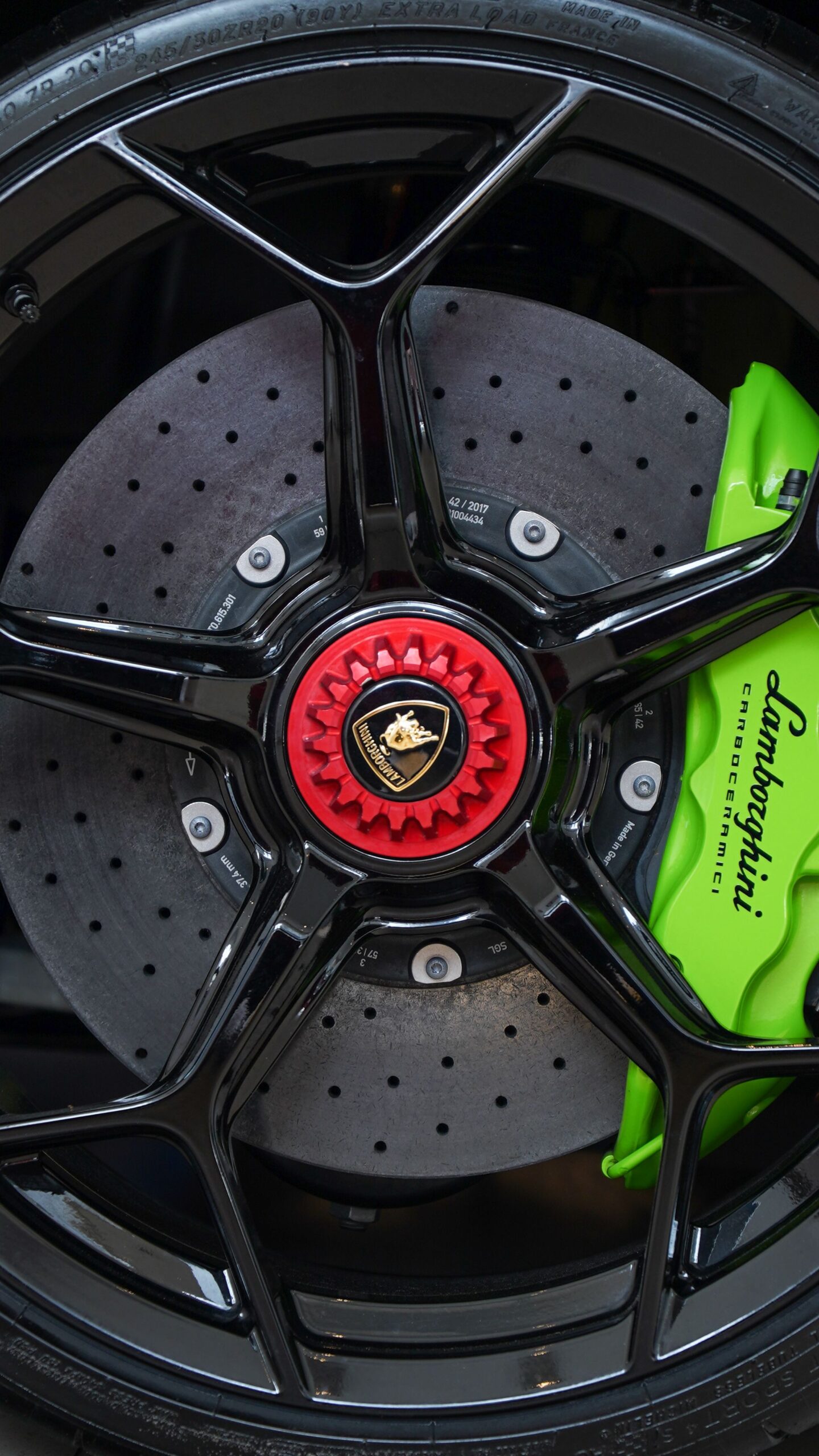
what is a brake assist system
Major Components of a Brake Assist System
The exact components depend on the system type, but most assisted braking arrangements contain several functional elements.
A control input initiates braking. This can be a brake pedal, push button, joystick, emergency-stop circuit, PLC command, or automated sequence.
A sensor or detection mechanism identifies the operating condition. Automotive systems may use pedal or pressure sensors. Industrial equipment can use speed sensors, limit switches, proximity sensors, or brake-position switches.
An assist mechanism generates additional force. Examples include vacuum boosters, hydraulic pumps, electric actuators, solenoids, or electromagnetic devices.
A braking mechanism converts that assistance into stopping or holding force. Depending on the application, it may be a disc brake, drum brake, hydraulic brake, electromagnetic brake, spring-applied brake, or mechanical holding brake.
A controller may coordinate the entire operation. In advanced marine equipment, this can involve PLCs, motor controllers, variable-frequency drives, safety relays, or dedicated control modules.
The power supply is also critical. A weak DC supply, loose terminal, damaged cable, blown fuse, or faulty relay can prevent the brake from releasing or applying correctly.
Finally, feedback and interlocks improve safety. These can confirm brake position, motor status, emergency-stop condition, or system readiness.
Types of Brake Assist Systems
There is no single design that represents every assisted braking system. Different applications require different technologies.
Vacuum Brake Assistance
Vacuum brake boosters are common in conventional automotive braking systems. They use a pressure differential to multiply the driver’s pedal force. The system allows the driver to achieve strong braking without applying extremely high physical force.
Hydraulic Brake Assistance
Hydraulic assistance uses fluid pressure to create or supplement braking force. These systems can be integrated with hydraulic pumps, valves, accumulators, and electronic controllers.
Electro-Hydraulic Braking
Electro-hydraulic systems combine electrical control with hydraulic force generation. An electronic controller can command a pump or valve to create the required pressure. These systems are useful when precise control and rapid response are important.
Electromagnetic Braking
Electromagnetic brakes use electrical energy to control mechanical braking. They are widely used in industrial machinery and can be found in lifting equipment, motors, conveyors, cranes, and winches.
Spring-Applied, Electrically Released Brakes
These brakes are particularly relevant to industrial and marine machinery. The brake is normally applied by spring force and electrically released. If electrical power fails, the brake can automatically engage, providing a fail-safe characteristic.
Regenerative or Dynamic Braking
Electric motor systems can also slow equipment through electrical braking. Variable-frequency drives and motor controllers may use dynamic or regenerative techniques depending on the application. These are not identical to conventional brake assist, but they are important parts of modern controlled stopping systems.
Brake Assist vs ABS: What Is the Difference?
Brake assist and ABS perform different jobs even though both are associated with emergency braking.
Brake assist primarily helps generate sufficient braking force during a rapid braking event. ABS, or anti-lock braking, controls wheel slip to prevent the wheels from locking under heavy braking.
For example, imagine a driver suddenly sees an obstacle. Brake assist can help increase braking pressure when the driver reacts quickly. ABS then modulates pressure at individual wheels if necessary to prevent lock-up.
The two technologies can therefore work together.
In industrial machinery, the equivalent relationship may be between a braking actuator and a separate control or safety system. One system may create the stopping force while another monitors speed, position, or operating conditions.
Marine electrical engineers should be careful not to assume that an automotive braking architecture can simply be transferred to marine machinery. The equipment duty cycle, load, environment, fail-safe requirements, classification requirements, motor characteristics, and control architecture all need to be considered.
For Electrical Marine Solutions, this is where electrical troubleshooting and control-system knowledge become valuable. A braking fault may not originate inside the brake itself. The actual problem could be in the control panel, PLC, sensor circuit, power supply, contactor, cable, or interlock.
Applications and Industries That Use Brake Assistance
Brake-assistance technologies are used across many industries where controlled deceleration or holding is necessary.
Automotive vehicles are the most familiar example. Passenger cars, commercial vehicles, buses, and other road vehicles can use different forms of assisted braking.
Industrial machinery is another major application. Cranes, hoists, elevators, conveyors, production machines, and motor-driven systems may use electromagnetic or spring-applied brakes.
Marine equipment can also require controlled braking. Deck cranes, cargo-handling machinery, winches, anchor-handling equipment, davits, lifting systems, and certain auxiliary machines may depend on mechanical brakes controlled through electrical circuits.
Offshore platforms have particularly demanding operating conditions. Equipment may need reliable braking under heavy loads, vibration, salt exposure, temperature changes, and continuous operation.
Mining, manufacturing, logistics, renewable energy, and material-handling industries also use controlled braking systems.
The engineering objective remains consistent: safely control motion, stop moving equipment, hold loads, and prevent unintended movement.
In these environments, braking must be integrated with the wider electrical architecture. Power distribution systems, motor starters, variable-frequency drives, PLC programming, safety circuits, emergency stops, and control panels may all interact with the braking system.
Brake Assist in Marine and Industrial Equipment
Marine braking systems require a different engineering perspective because ships and offshore installations operate in harsh environments. Saltwater exposure, humidity, vibration, temperature variation, mechanical shock, and restricted access can affect electrical and mechanical equipment.
A brake used on a marine winch may be electrically controlled. When the operator commands movement, the control circuit may energize a brake-release coil. Once the brake is released, the motor can rotate. When the movement command is removed, the brake may apply.
A typical control sequence could involve the PLC receiving a start command, checking safety interlocks, energizing the brake-release circuit, confirming brake feedback, and then permitting motor operation.
If the brake feedback does not arrive within the expected time, the PLC may stop the motor and generate an alarm.
This is a good example of why Marine Automation and PLC Programming are closely related to equipment safety. A mechanical brake may be perfectly healthy while an electrical fault prevents it from operating.
Common electrical causes include damaged cables, corroded terminals, failed relays, incorrect voltage, defective contactors, damaged coils, sensor failures, PLC output problems, or poor grounding.
Professional Electrical Troubleshooting should therefore examine the complete system instead of replacing components without testing.
Step-by-Step Brake Assist Operating Process
A typical controlled braking sequence can be understood through the following steps.
Step 1: Command Detection
The system receives a braking command from the operator or automated controller. This could be a pedal movement, stop button, joystick command, PLC output, or emergency-stop signal.
Step 2: Condition Verification
The controller checks whether required safety conditions are satisfied. Interlocks, emergency circuits, sensor signals, and system status may be evaluated.
Step 3: Assistance Activation
The braking assist mechanism becomes active. Depending on the system, this may mean increasing hydraulic pressure, activating an electric actuator, or removing power from a spring-applied brake.
Step 4: Brake Engagement
The physical braking mechanism creates friction or holding force. Moving equipment begins to decelerate or stops completely.
Step 5: Feedback Confirmation
A sensor or switch can confirm that the brake has engaged. In automated machinery, the controller may use this feedback before permitting another operation.
Step 6: Fault Monitoring
If the expected feedback does not arrive, the control system can generate an alarm or prevent further operation.
Step 7: Safe Reset
After the fault or emergency condition is resolved, the system should be reset according to the manufacturer’s procedure and applicable safety requirements.
Brake Assist Inspection Procedure
Inspection should always begin with the manufacturer’s technical documentation, equipment drawings, and applicable safety procedures.
The first stage is a visual inspection. Look for damaged cables, loose terminals, corrosion, oil contamination, overheating, cracked housings, abnormal wear, and signs of mechanical damage.
Next, inspect the brake actuator and associated wiring. An electromagnetic brake coil, for example, should be checked for physical damage and signs of overheating.
The electrical supply should then be verified. Measure the control voltage at the appropriate test points using properly rated instruments. A control device may require a specific DC or AC voltage, so the manufacturer’s specification should be followed.
Inspect relays, contactors, fuses, circuit breakers, terminals, connectors, and emergency-stop circuits.
If a PLC is involved, review input and output status. Determine whether the controller is receiving the correct command and whether it is producing the expected output.
Feedback sensors should also be tested. A brake-position switch that remains permanently open or closed can cause false alarms or prevent operation.
Finally, mechanical inspection should verify brake adjustment, friction surfaces, springs, linkages, and physical movement.
Never bypass a safety interlock merely to make equipment operate. A bypass can hide the actual fault and create a dangerous condition.
Brake Assist Testing Methods
Testing should be systematic rather than based on component replacement.
Visual testing is the first method. Inspect wiring, terminals, housings, connectors, coils, and mechanical parts.
Voltage testing determines whether the correct supply reaches the relevant component. Always use the correct measurement points and follow electrical safety procedures.
Continuity testing can help identify open circuits, broken conductors, and failed switches, but continuity measurements should be performed only when the circuit is safely isolated and de-energized.
Resistance testing may help identify abnormal coil or winding conditions. Compare measured values with the manufacturer’s specifications rather than relying on generic resistance numbers.
Insulation testing can be useful for suitable motor and cable circuits when performed by qualified personnel using the correct test procedure.
Functional testing verifies that the brake applies and releases correctly.
Feedback testing confirms that sensors and switches provide the expected signal to the control system.
PLC diagnostic testing can identify whether the controller receives the correct inputs and produces the correct outputs.
Testing should always progress from simple observations to more detailed electrical and mechanical analysis.
Common Brake Assist Problems and Warning Signs
A brake system can develop mechanical, electrical, hydraulic, or electronic faults.
One common symptom is increased stopping effort. In an automotive system, this may indicate a problem with the assistance mechanism. In industrial equipment, excessive braking effort can indicate actuator or control problems.
A brake that remains applied may be caused by incorrect control voltage, a failed release coil, mechanical seizure, damaged wiring, or an incorrect PLC output.
A brake that fails to apply is potentially more serious. Possible causes include a defective spring mechanism, actuator failure, incorrect control logic, damaged brake relay, or a safety circuit fault.
Intermittent operation often points toward loose terminals, corrosion, vibration-related wiring damage, failing sensors, overheating components, or unstable power supplies.
Warning alarms should never be ignored. Repeated brake-related alarms can indicate a developing problem even when the machinery continues to operate.
Unusual noise, excessive heat, delayed brake release, inconsistent stopping, unexpected movement, or repeated control-system trips should be investigated promptly.
For marine equipment, corrosion deserves particular attention. Moisture and salt contamination can increase contact resistance and damage electrical connections, creating intermittent faults that are difficult to reproduce.
Brake Assist Troubleshooting Guide
Effective troubleshooting follows a logical sequence.
Start by confirming the reported symptom. Determine whether the brake does not apply, does not release, applies slowly, releases intermittently, or produces an alarm.
Next, check the system documentation. Electrical drawings and control schematics can reveal how the brake circuit is supposed to operate.
Then inspect the power supply. Confirm that the relevant voltage is present and stable.
After that, trace the control signal from the command device through relays, contactors, PLC outputs, connectors, and the actuator.
If the control voltage reaches the brake actuator but the brake does not respond, investigate the actuator and mechanical mechanism.
If the actuator receives no voltage, move backward through the control circuit until the missing signal is identified.
For PLC-controlled equipment, check the input conditions, logic status, output command, interlocks, alarms, and feedback signals.
For marine equipment, also inspect cable glands, junction boxes, terminal blocks, and connectors for moisture or corrosion.
Do not replace a PLC, motor, brake coil, or controller simply because it appears suspicious. Confirm the failure with measurements.
A professional electrical fault-finding process should identify the root cause rather than merely replacing the failed symptom.
Preventive Maintenance for Brake Assist Systems
Preventive maintenance is one of the most effective ways to reduce unexpected braking failures, and understanding what is a brake assist system helps maintenance teams identify the components and control functions that require regular inspection.
Maintenance intervals for what is a brake assist system should be based on equipment manufacturer recommendations, operating hours, environmental conditions, duty cycle, and safety requirements. Different marine and industrial applications may require different inspection schedules.
Inspect the electrical connections associated with what is a brake assist system regularly. Tighten loose terminals according to appropriate specifications and replace damaged cables, connectors, relays, or other components when necessary.
Check brake actuators used within what is a brake assist system for overheating, contamination, unusual noise, delayed operation, and physical wear. Early identification of these symptoms can help prevent more serious failures.
Inspect control cabinets that support what is a brake assist system for corrosion, dust, moisture, excessive temperature, and loose wiring. Clean and maintain enclosures according to the manufacturer’s recommendations.
For marine systems, inspect cable glands and enclosure seals carefully when maintaining what is a brake assist system. Water ingress can cause insulation deterioration, corrosion, short circuits, and intermittent control faults that may be difficult to diagnose.
Test emergency-stop functions and safety interlocks connected to what is a brake assist system according to the equipment’s approved procedure. Never bypass safety devices simply to make a system operate during testing.
Review PLC alarms and historical fault information related to what is a brake assist system. Repeated alarms may reveal developing problems before an actual brake failure occurs and can provide valuable information for electrical troubleshooting.
Generator and motor maintenance can also support the reliability of what is a brake assist system because unstable electrical power may affect control circuits, electromagnetic actuators, sensors, and other braking components. A documented Preventive Maintenance program should record inspection dates, measured values, faults found, corrective actions, replacement parts, and test results.
Safety Precautions When Working on Brake Systems
Understanding what is a brake assist system is especially important when working around braking equipment because these systems can store mechanical, hydraulic, pneumatic, and electrical energy. Maintenance therefore requires careful isolation and a clear understanding of all potential energy sources.
Before working on what is a brake assist system or its associated control equipment, identify all energy sources. Electrical supplies, hydraulic pressure, pneumatic pressure, suspended loads, rotating machinery, and stored mechanical energy may all create serious hazards.
When servicing what is a brake assist system in industrial or marine equipment, apply appropriate lockout/tagout procedures before accessing energized or moving equipment. Proper isolation ensures that unexpected movement or energy release does not occur during maintenance.
Never work underneath a suspended load simply because a brake appears engaged. When inspecting or testing what is a brake assist system, never bypass emergency stops, safety relays, door switches, overload protection, or brake feedback solely to complete a test.
Use properly rated electrical test instruments and appropriate personal protective equipment when working on what is a brake assist system or any connected control circuit. Technicians should follow the manufacturer’s procedures and applicable electrical safety requirements.
When testing what is a brake assist system in an industrial or marine environment, establish clear communication between the technician and equipment operator. Everyone involved should understand when equipment may be energized, moved, stopped, or tested.
After maintenance, verify that all protective devices associated with what is a brake assist system have been restored and that all tools, temporary connections, test leads, and bypasses have been removed. A functional test should then be performed in a controlled environment before returning equipment to normal operation.
Marine electrical systems can be particularly unforgiving because equipment associated with what is a brake assist system may be located in confined spaces or near conductive, wet environments. Safety procedures should therefore be treated as an essential part of the engineering process, not an administrative formality.
Repair vs Replacement: Which Is Better?
The decision to repair or replace a brake component depends on the nature of the failure, equipment age, availability of parts, safety requirements, and total repair cost.
Repair may be appropriate when the fault is caused by a damaged cable, loose connection, defective relay, corroded terminal, faulty sensor, or another replaceable electrical component.
Replacement may be more appropriate when the actuator has suffered severe overheating, insulation failure, mechanical damage, excessive wear, or repeated failures.
For critical marine equipment, reliability should carry significant weight. A component that can technically be repaired may still be unsuitable if its reliability cannot be demonstrated.
Electrical engineers should also consider compatibility. Replacing a brake actuator with a component having the wrong voltage, current, response characteristics, mechanical dimensions, or control interface can create a new safety problem.
Before replacement, investigate the root cause. If a brake coil failed because of excessive voltage, installing another identical coil without correcting the supply problem will probably lead to another failure.
The best approach is therefore diagnose first, repair where appropriate, replace when justified, and test the complete system afterward.
Brake Assist System Cost Factors
The cost of diagnosing or repairing a braking system depends heavily on the system’s complexity.
A simple electrical fault such as a loose terminal or damaged wire may be inexpensive to correct. A failed sensor or relay may also be relatively straightforward.
More complex problems can involve PLC programming, control-panel troubleshooting, motor drives, hydraulic components, brake actuators, or specialized control modules.
Marine environments can increase costs because technicians may need to work aboard vessels, offshore installations, or difficult-access machinery. Emergency callouts, vessel downtime, specialist equipment, and replacement-part availability can also influence the final cost.
The cost of the brake component itself is only one part of the overall expense. Diagnosis, labor, transportation, testing, commissioning, documentation, and downtime should also be considered.
For commercial vessels and industrial facilities, preventive maintenance can often be more economical than waiting for a critical brake fault to stop operations.
A professional service provider should ideally identify the problem before recommending expensive replacement work. A clear diagnostic report can help equipment owners make an informed repair-versus-replacement decision.
Future Trends in Braking and Control Systems
Braking technology is increasingly becoming software-controlled, sensor-driven, and integrated with broader automation platforms. Understanding what is a brake assist system is becoming more important as braking equipment evolves from traditional mechanical mechanisms into intelligent systems that combine sensors, electronics, controllers, and automated safety functions.
Electric vehicles are accelerating the development of electronically controlled braking and regenerative braking. A clear understanding of what is a brake assist system helps explain how sensors, electronic controllers, electric actuators, hydraulic systems, and advanced diagnostic functions work together to improve braking performance and system reliability.
Industrial automation is following a similar path. Modern smart braking equipment can provide condition information, operating-hour data, temperature information, and fault signals to supervisory systems. This makes what is a brake assist system an increasingly relevant topic for engineers working with automated machinery and intelligent motor-control systems.
In marine environments, this trend aligns closely with digital ship systems and Marine Automation. Understanding what is a brake assist system can help engineers recognize how PLCs, remote monitoring, industrial networks, motor drives, and centralized control systems can exchange information about braking equipment and overall machine status.
Predictive maintenance is another important development. Instead of waiting for a brake to fail, monitoring systems can identify unusual temperature, current, response time, vibration, or operating patterns. This approach provides valuable information for determining what is a brake assist system doing during normal operation and whether its performance is beginning to change.
Condition-based maintenance can then be scheduled before the equipment reaches a critical failure condition. When engineers understand what is a brake assist system and monitor its operating parameters, maintenance teams can identify developing problems earlier and plan corrective work more effectively.
For marine electrical engineers, the future is therefore not simply about repairing brakes. Understanding what is a brake assist system increasingly means integrating braking equipment into reliable, measurable, diagnosable, and fail-safe control architectures.
As marine automation continues to develop, the practical meaning of what is a brake assist system will increasingly include intelligent monitoring, digital diagnostics, PLC integration, remote condition monitoring, and predictive maintenance, helping vessels and industrial facilities improve equipment reliability while reducing unexpected downtime.
Why Trust Electrical Marine Solutions
Electrical Marine Solutions approaches marine and industrial electrical work from a systems perspective. Understanding what is a brake assist system requires recognizing that reliable equipment performance depends on more than a single component; power distribution, motors, controls, automation, sensors, protection devices, and mechanical equipment must work together.
The company’s service focus is highly relevant to understanding what is a brake assist system in complex marine and industrial environments. Its services include Marine Electrical Services, Electrical Troubleshooting, Electrical Fault Finding, Marine Automation, Switchboard Maintenance, Generator and Motor Repairs, PLC Programming, Control Systems, Power Distribution Systems, Preventive Maintenance, Emergency Electrical Repairs, and Industrial Electrical Engineering solutions.
This broad technical scope becomes particularly important when determining what is a brake assist system and troubleshooting equipment with integrated electrical and mechanical functions. A braking problem may involve several interconnected components rather than the brake assembly alone.
Experienced Marine Electrical Engineers can apply their knowledge of what is a brake assist system by examining the complete control path rather than immediately replacing the brake itself. Advanced diagnostic equipment can help identify voltage abnormalities, wiring faults, control-signal problems, sensor issues, and equipment failures.
Safety is equally important when working with what is a brake assist system and related control equipment. Marine and industrial electrical systems often operate around high-energy equipment, rotating machinery, generators, motors, lifting equipment, and complex control systems. Engineering best practices and proper isolation procedures are essential.
Electrical Marine Solutions can apply its understanding of what is a brake assist system within a wider preventive-maintenance strategy. Instead of treating each fault as an isolated emergency, equipment owners can use inspection, testing, documentation, and condition monitoring to improve reliability.
For vessels, offshore installations, and industrial facilities, understanding what is a brake assist system can help maintenance teams recognize how braking equipment interacts with electrical and automation systems. This systems-based approach can help reduce unexpected downtime and support safer equipment operation.
By combining knowledge of what is a brake assist system with Marine Automation, PLC Programming, Electrical Troubleshooting, and Control Systems expertise, engineers can investigate faults more systematically and identify potential problems before they become major failures.
A professional approach to what is a brake assist system also means considering the complete operating environment. Marine conditions such as salt exposure, humidity, vibration, temperature changes, and continuous equipment operation can affect electrical and mechanical components over time.
Ultimately, knowing what is a brake assist system is only one part of maintaining reliable braking equipment. The greater objective is to understand how the brake, actuator, sensors, control circuit, power supply, PLC, and safety systems interact so that equipment can operate safely and reliably.
Maintenance Checklist
A practical brake-control maintenance checklist should include the following:
- Inspect brake assemblies for visible mechanical damage.
- Check electrical cables for cuts, abrasion, and insulation deterioration.
- Inspect terminals and connectors for looseness or corrosion.
- Verify control voltage against manufacturer specifications.
- Check relays, contactors, fuses, and circuit breakers.
- Inspect electromagnetic brake coils for overheating.
- Test brake-position feedback sensors.
- Review PLC input and output status where applicable.
- Test emergency-stop circuits.
- Verify safety interlocks.
- Inspect control cabinets for moisture and contamination.
- Check cable glands and enclosure seals on marine equipment.
- Record abnormal noise, heat, vibration, or delayed response.
- Review historical alarms and fault records.
- Perform functional testing after maintenance.
- Document measurements and corrective actions.
- Schedule follow-up inspection if deterioration is detected.
A checklist is most useful when technicians record actual findings rather than simply ticking boxes. Measured voltage, resistance, temperature, response time, and fault history can help identify trends over time.
Inspection Checklist
A professional inspection should cover four major areas: mechanical, electrical, control, and safety.
Mechanical: inspect brake surfaces, springs, linkages, bearings, mounting hardware, and signs of wear.
Electrical: inspect cables, terminals, coils, relays, contactors, fuses, power supplies, and grounding arrangements.
Control: verify PLC inputs, outputs, sensors, interlocks, emergency-stop signals, alarms, and feedback circuits.
Safety: confirm that protective devices work correctly and that no unauthorized bypasses exist.
For marine systems, add environmental inspection. Look for salt deposits, moisture, corrosion, water ingress, damaged cable glands, and condensation inside electrical enclosures.
Inspection results should be documented in a maintenance record. This provides useful information for future troubleshooting and helps engineers recognize recurring faults.
Professional Tips From a Marine Electrical Perspective
One of the most important troubleshooting principles when understanding what is a brake assist system is to avoid assuming that the failed component is automatically the root cause. A proper diagnosis should examine the complete braking and control system rather than focusing on one component.
If an electromagnetic brake coil burns out, understanding what is a brake assist system helps engineers investigate why the failure occurred. Excessive voltage, incorrect control logic, prolonged energization, mechanical overload, poor ventilation, or a defective control device may have caused the failure.
Another important principle when examining what is a brake assist system is understanding the equipment’s fail-safe philosophy. Some industrial and marine brakes are designed to engage when electrical power is lost, while others may use different operating arrangements. Never assume how a brake behaves during power failure.
Always consult the electrical schematic when determining what is a brake assist system and before testing a complex control circuit. The schematic helps identify the correct power supply, control path, safety interlocks, sensors, relays, contactors, and brake actuator connections.
When PLCs are involved, understanding what is a brake assist system also requires comparing the actual operating sequence with the intended control logic. A programming or logic error can produce symptoms that appear to be hardware failures.
Finally, understanding what is a brake assist system in a marine environment requires attention to the effects of corrosion, moisture, vibration, and salt exposure. Corrosion prevention, enclosure inspection, cable protection, and preventive maintenance should therefore receive particular attention.
A good engineer understands what is a brake assist system as part of a complete electrical and mechanical control system rather than simply making equipment run again. The objective is to identify why the fault happened, restore the system safely, verify correct operation, and reduce the likelihood of recurrence.
FAQs
What is a brake assist system and why is it important?
A brake assist system helps increase braking force during rapid or emergency braking. It is important because an operator may react quickly but fail to apply enough physical force to achieve maximum braking performance. The assistance mechanism helps the braking system respond more effectively during situations where fast deceleration is required.
Is brake assist the same as ABS?
No. Brake assist and ABS perform different functions. Brake assist helps provide or increase braking force during emergency braking, while ABS controls wheel slip to reduce the possibility of wheel lock. Modern vehicles can use both technologies together so that braking force is quickly established while wheel lock is controlled.
How does brake assist work?
Brake assist detects characteristics associated with emergency braking and helps the braking system generate greater force. Depending on the design, assistance may come from a vacuum booster, hydraulic pump, electric actuator, or electronic control system. Industrial equipment may use similar principles through electromagnetic brakes, hydraulic actuators, or PLC-controlled braking circuits.
Does brake assist reduce stopping distance?
Brake assist can help reduce stopping distance when the operator would otherwise fail to apply sufficient braking force during an emergency. Its effectiveness depends on vehicle speed, road conditions, tire grip, brake condition, system design, and how quickly the assistance activates. It cannot overcome physical traction limitations.
Can brake assist fail?
Yes. Brake assistance can fail because of electrical, mechanical, hydraulic, vacuum, sensor, actuator, or control-system problems. Warning signs may include increased pedal effort, delayed braking response, warning lights, unusual noises, intermittent operation, or abnormal system behavior. Any significant braking fault should be professionally inspected.
What causes brake assist failure?
Possible causes include damaged sensors, faulty actuators, vacuum problems, hydraulic faults, electrical wiring damage, defective relays, control-module faults, low voltage, corroded connections, or mechanical wear. In industrial equipment, PLC outputs, interlocks, brake coils, contactors, and feedback switches can also cause braking-control failures.
Can brake assist be found in marine equipment?
The exact automotive-style system is not normally applicable to every marine vessel, but related braking-assistance and controlled-braking technologies are widely relevant to marine machinery. Winches, cranes, hoists, davits, and deck equipment can use electromagnetic, hydraulic, or spring-applied brakes controlled through electrical systems.
Why are electrical controls important for marine brakes?
Electrical controls determine when many marine brakes release or engage. Control circuits can include switches, relays, contactors, PLC outputs, sensors, safety interlocks, and feedback devices. A mechanical brake may be healthy while an electrical fault prevents it from operating, which is why electrical troubleshooting is essential.
What is an electromagnetic brake?
An electromagnetic brake is a brake controlled using an electromagnetic actuator. Depending on its design, electrical power may release or engage the brake. Electromagnetic brakes are common in industrial motors, cranes, hoists, conveyors, winches, and other machinery where rapid and controlled stopping or holding is required.
What is a spring-applied brake?
A spring-applied brake uses mechanical spring force to apply the brake and electrical or hydraulic force to release it. This arrangement can provide a fail-safe characteristic because loss of electrical power can cause the brake to engage. The actual safety behavior must always be verified against the equipment manufacturer’s design.
How do you troubleshoot a brake control circuit?
Begin by confirming the symptom and reviewing the electrical schematic. Check the power supply, fuses, relays, contactors, switches, sensors, PLC inputs and outputs, actuator voltage, and feedback signals. Then inspect the mechanical brake. Testing should progress logically so the actual root cause is identified rather than simply replacing components.
How often should a brake system be inspected?
Inspection frequency depends on equipment type, manufacturer recommendations, operating hours, environment, load, and safety requirements. Marine and offshore equipment may require more frequent inspection because vibration, humidity, salt exposure, and heavy duty cycles can accelerate deterioration. A documented preventive-maintenance program should define appropriate intervals.
Can a PLC control a brake system?
Yes. PLCs can control industrial and marine braking sequences by receiving commands and sensor feedback and activating outputs connected to relays, contactors, solenoids, or brake actuators. PLC logic can also enforce safety interlocks and prevent motor operation when the required brake status is not confirmed.
What should I do if a brake warning appears?
Do not ignore a brake warning. Stop using the equipment when it is safe to do so and follow the manufacturer’s emergency or maintenance procedure. Continued operation with an unresolved braking fault can create a serious safety risk. A qualified technician should diagnose the system before normal operation resumes.
Is brake repair better than replacement?
It depends on the fault. Wiring, sensors, terminals, relays, and some control components may be repairable or replaceable individually. Severely damaged or repeatedly failing brake assemblies may be better replaced. The decision should consider safety, reliability, availability of parts, equipment age, downtime, and the root cause of failure.
How can marine brake failures be prevented?
Preventive maintenance is the best approach. Regularly inspect wiring, terminals, brake actuators, sensors, control panels, cable glands, and feedback circuits. Test safety interlocks and emergency stops, monitor alarms, protect electrical equipment from moisture and corrosion, and document faults. Condition-based monitoring can provide additional early warning.
When should I call a marine electrical engineer?
Call a qualified Marine Electrical Engineer when a braking problem involves control panels, PLCs, motor drives, high-voltage equipment, complex wiring, emergency systems, or repeated electrical faults. Professional support is especially important when equipment operates on commercial vessels, offshore platforms, cranes, winches, or other safety-critical machinery.
Can a brake-control fault cause motor problems?
Yes. Brake and motor-control circuits are often interconnected. If the brake does not release correctly, the motor may be unable to start or may experience excessive load. Conversely, an incorrect motor-control sequence can affect brake operation. Proper diagnosis should therefore consider both the brake circuit and the associated motor-control system.
What role does preventive maintenance play in braking reliability?
Preventive maintenance identifies deterioration before it becomes a critical failure. Inspecting electrical connections, testing sensors, checking actuator condition, reviewing alarms, and verifying safety circuits can reduce unexpected downtime. In marine environments, preventive maintenance is particularly valuable because corrosion and difficult access can make emergency repairs more complicated.
Final Takeaways
Understanding what is a brake assist system requires more than knowing that it provides additional braking force. To fully understand what is a brake assist system, it is important to consider the combination of mechanical engineering, hydraulics, electrical control, sensors, electronics, automation, and safety logic that makes modern braking technology effective.
In automotive applications, understanding what is a brake assist system helps explain how brake assistance supports drivers during emergency braking. In industrial and marine environments, understanding what is a brake assist system is also useful because related braking technologies can control motors, winches, cranes, hoists, and deck machinery.
The most important lesson when considering what is a brake assist system is that braking faults should be diagnosed as complete system faults. A problem may originate in the brake mechanism, but it can also come from a power supply, cable, relay, sensor, PLC, contactor, actuator, or safety interlock.
For commercial vessels and offshore installations, understanding what is a brake assist system is particularly relevant when reliable braking and holding functions are essential to safe operation. Regular inspection, electrical fault finding, preventive maintenance, and proper functional testing are therefore critical.
Electrical Marine Solutions can support these requirements through Marine Electrical Services, Electrical Troubleshooting, Marine Automation, Switchboard Maintenance, Generator and Motor Repairs, PLC Programming, Control Systems, Power Distribution Systems, Preventive Maintenance, Emergency Electrical Repairs, and Industrial Electrical Engineering solutions. By understanding what is a brake assist system and how its electrical and control components interact, engineers can identify faults more accurately and improve overall equipment reliability.
Call to Action
If your vessel, offshore installation, or industrial facility is experiencing electrical control problems, motor faults, switchboard issues, automation failures, or braking-control problems, professional diagnosis can prevent a small fault from becoming expensive downtime.
Contact Electrical Marine Solutions for professional Marine Electrical Services, Electrical Troubleshooting, Electrical Fault Finding, Marine Automation, Generator Repairs, Motor Repairs, Switchboard Maintenance, PLC Programming, Preventive Maintenance, Control Systems, Power Distribution, and Industrial Electrical Engineering support.
A properly tested system is safer, more reliable, and easier to maintain. Instead of repeatedly replacing failed components, identify the root cause and restore the complete electrical and control system to reliable operation.
